
Filament Sinkage Rate Calibration Model
Print Profile(2)

Description
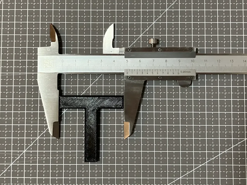
The primary shrinkage direction of the filament is the extrusion direction, which is also the model texture direction,
this test will be based on this principle to calibrate the filament shrinkage rate
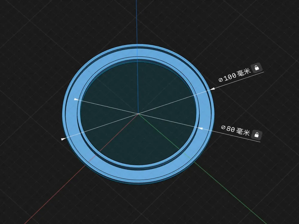
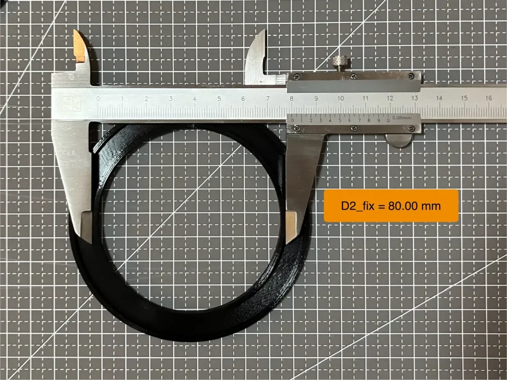
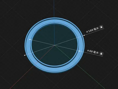
The test sample consists of two concentric rings with a diameter of D1 = 100mm and D2 = 80mm and a width of 2mm sharing a common base
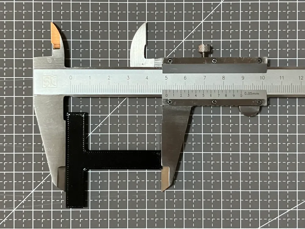
If you are unable to accurately measure the circular diameter, you can also use the octagonal ring on the second plate (with some error) as a substitute
 or
or 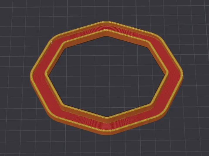
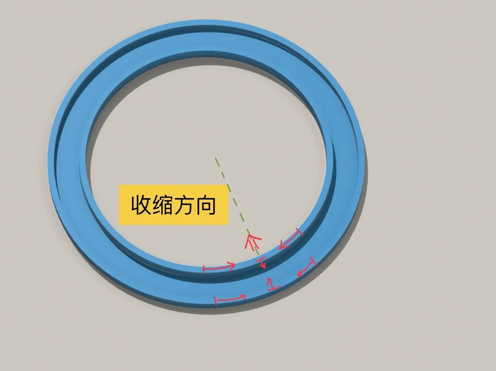
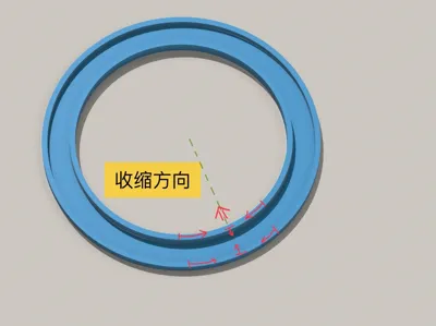
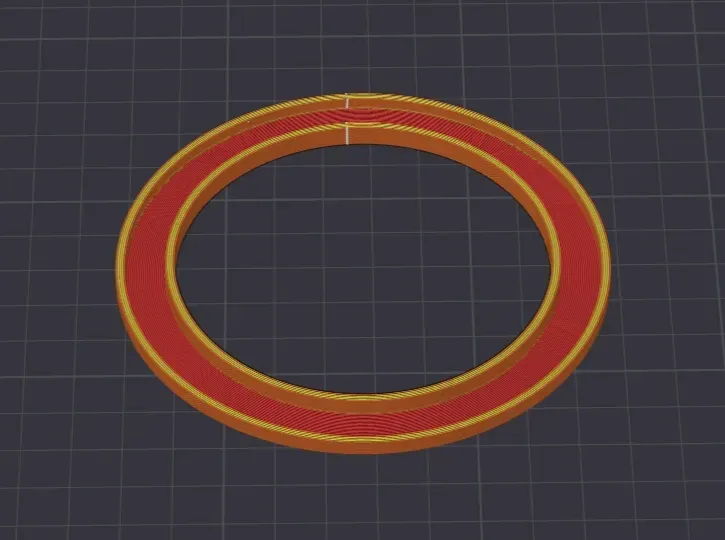
The calibration should use the outer diameter of the ring, using the inner diameter will result in inaccuracies due to centrifugal stress as shown below
This mitigates shrinkage, affecting calibration accuracy
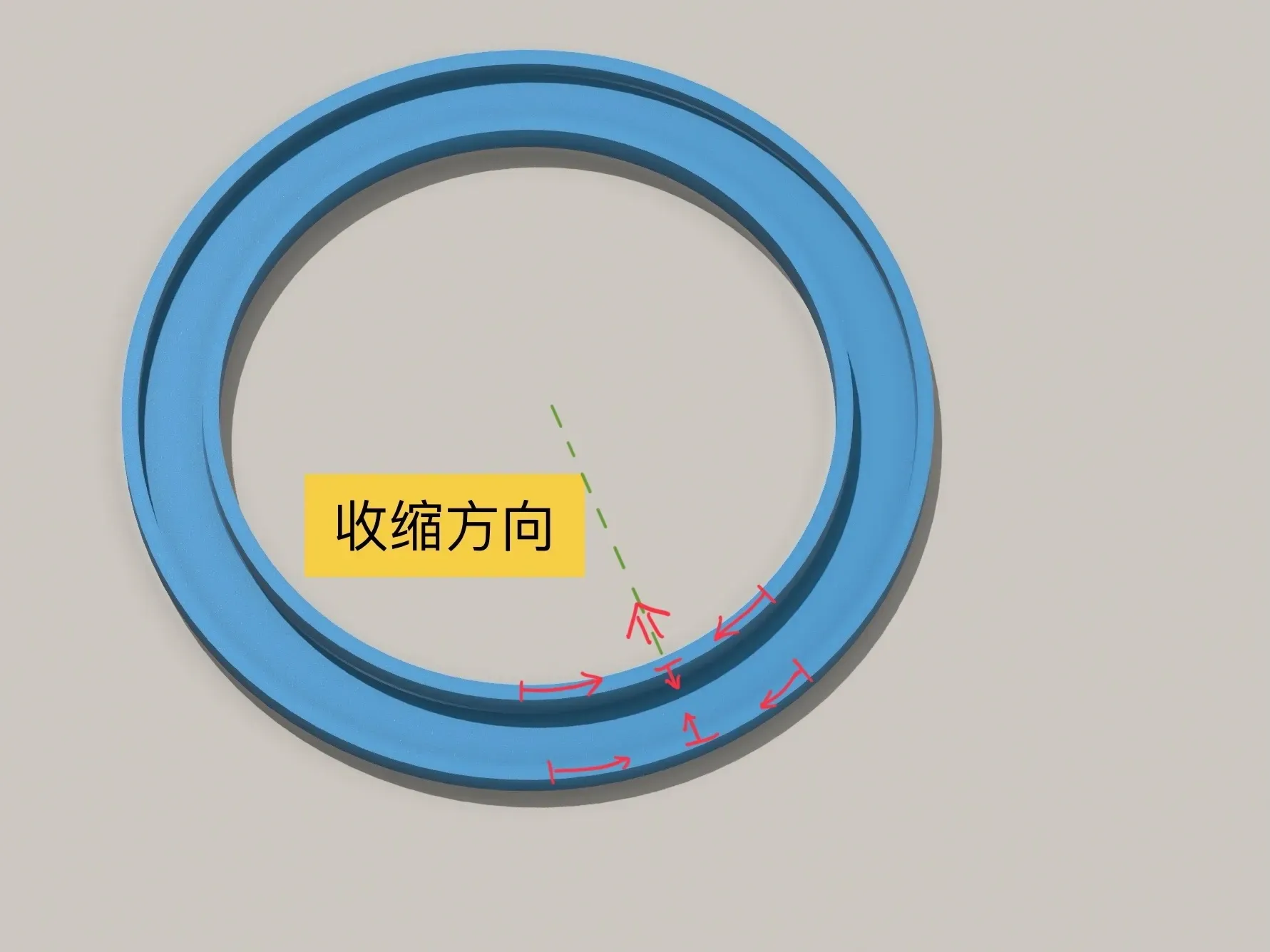
Additionally, if you need to calibrate the aperture, perform hole size compensation after calibrating the filament shrinkage rate
Calibration method: (Allow the test ring to cool to room temperature before measurement)
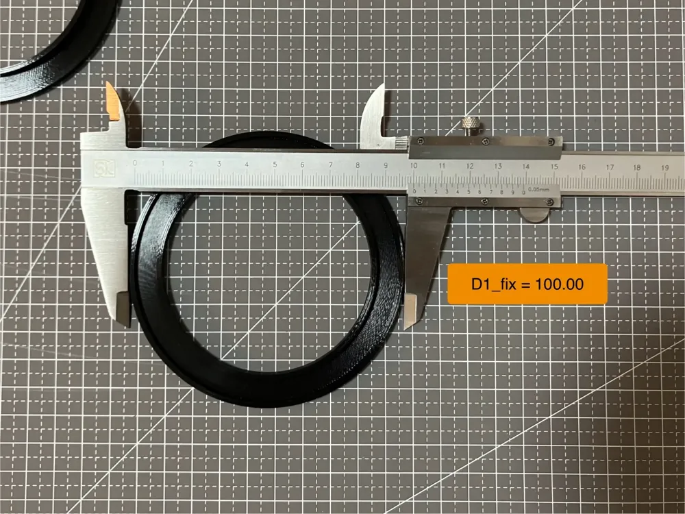
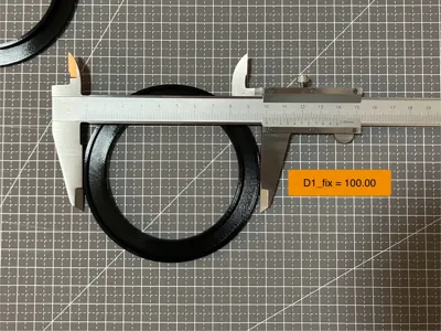
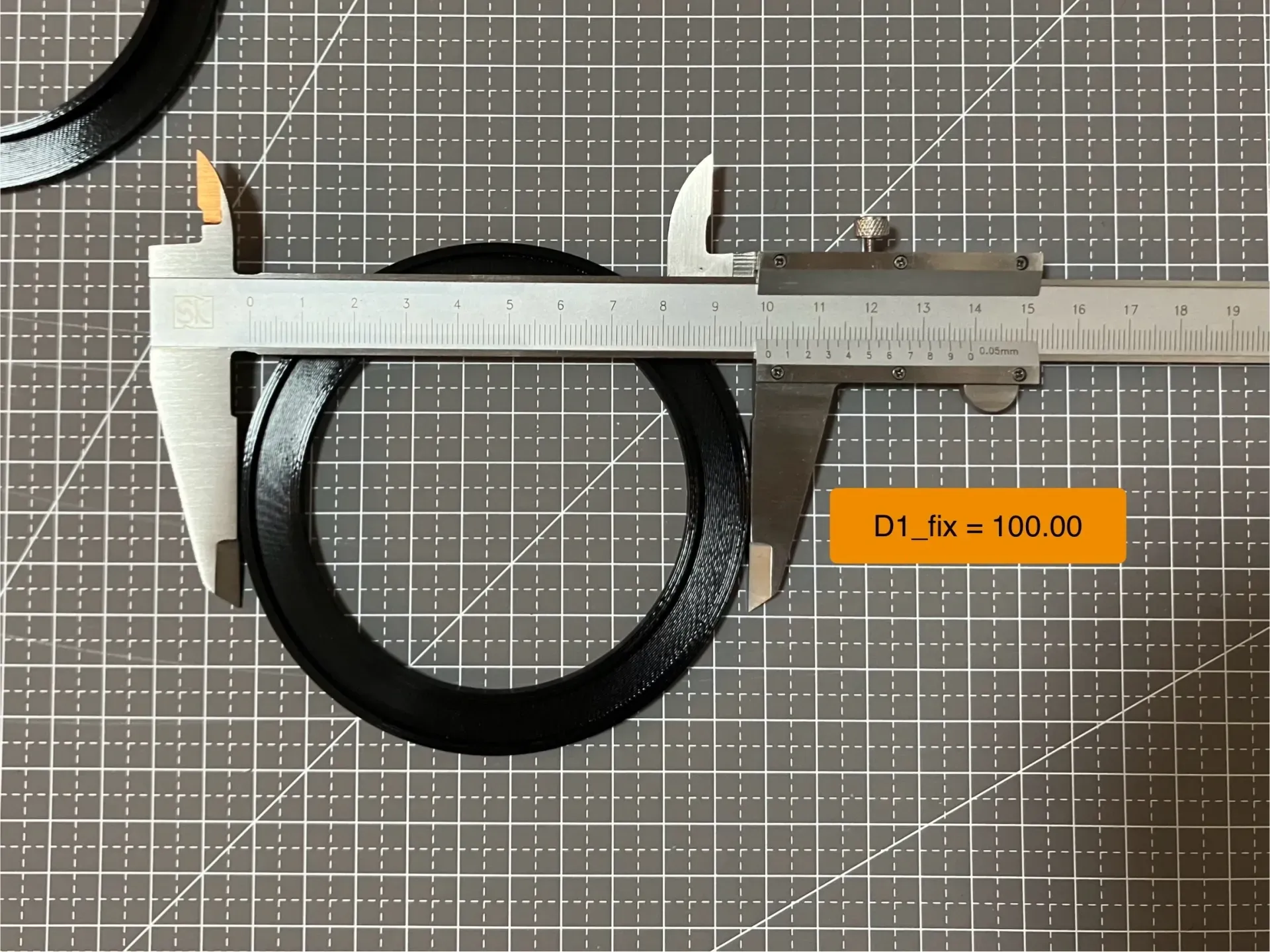
- Measure the outer 100mm diameter multiple times, take the average, and set it as D1 (if only performing a rough measurement, use this value directly as the shrinkage rate)
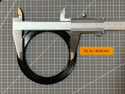
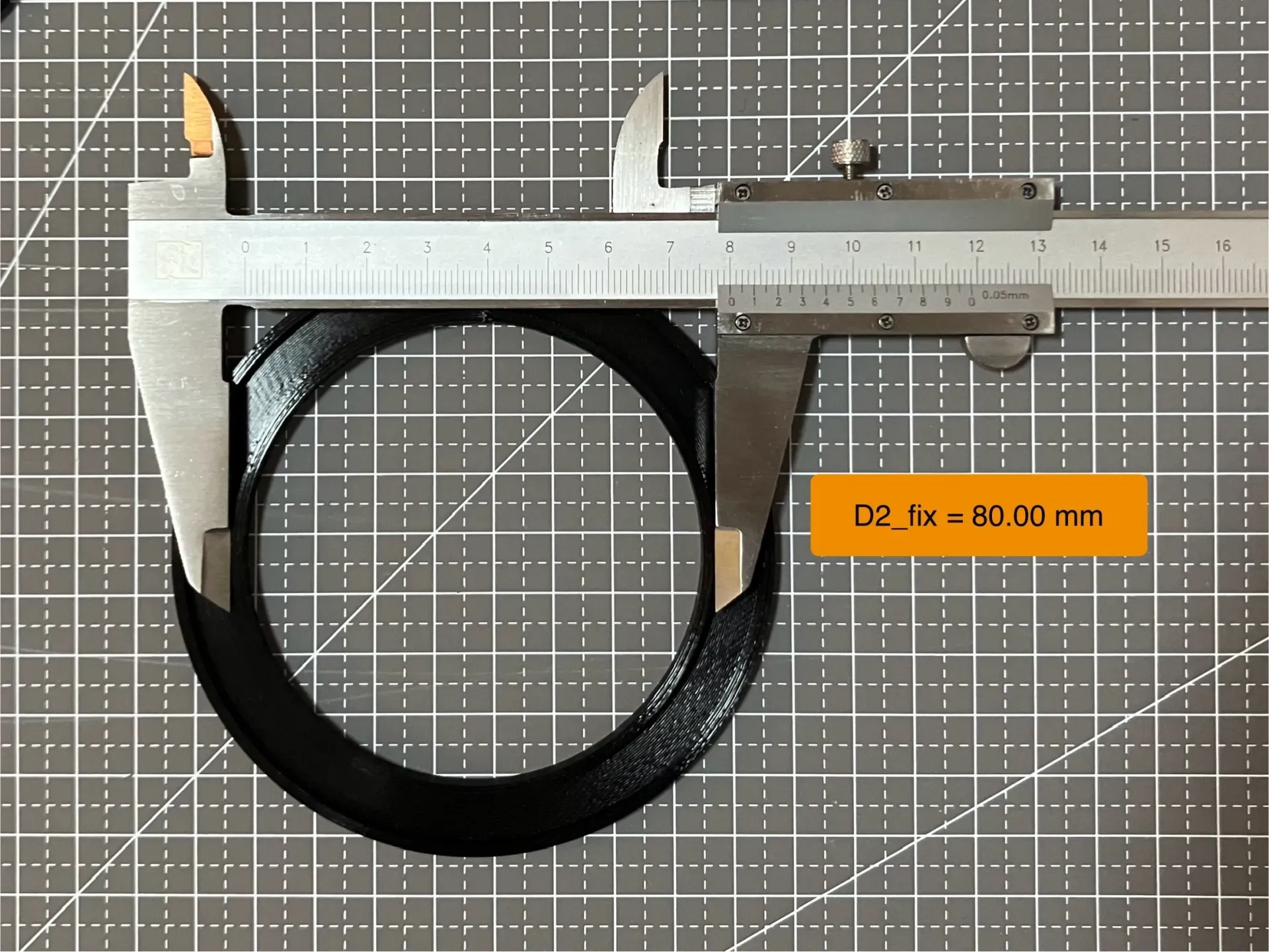
- Measure the inner 80mm diameter multiple times, take the average, and set it as D2
- Calibrated shrinkage rate = 3/5 x D1 +2/5 x 100/80 x D2 (weighting is an empirical value)
- In the software, after changing the filament shrinkage rate, print the test sample or reprint the test ring to verify the calibration
- If there is a deviation after calibration, update the shrinkage rate = old shrinkage rate x secondary calibration shrinkage rate
~~~~~~~~~~ ~~~~~~~~~~ Divider ~~~~~~~~~~ ~~~~~~~~~~
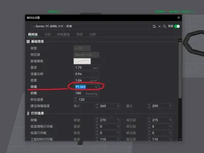
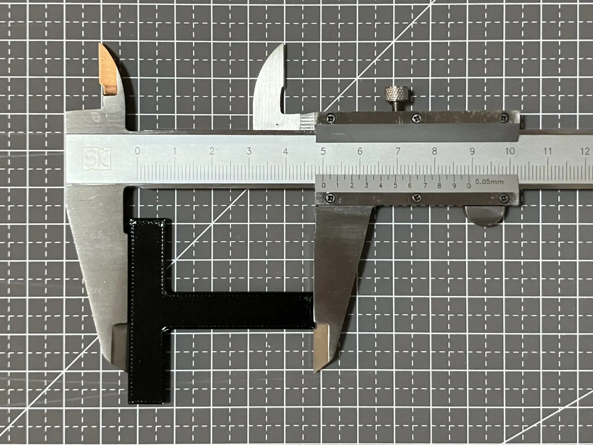
Below, I will calibrate the shrinkage rate using black PC filament as an example:
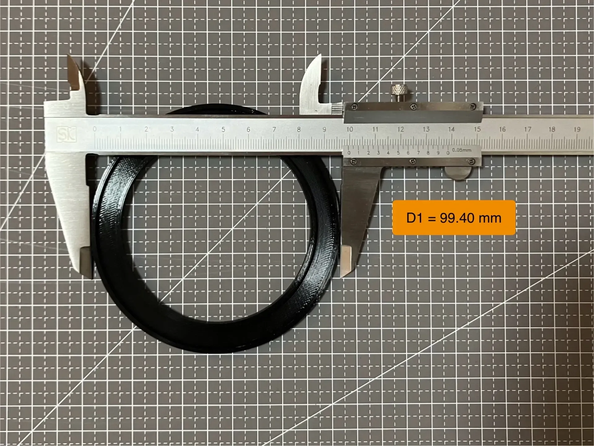
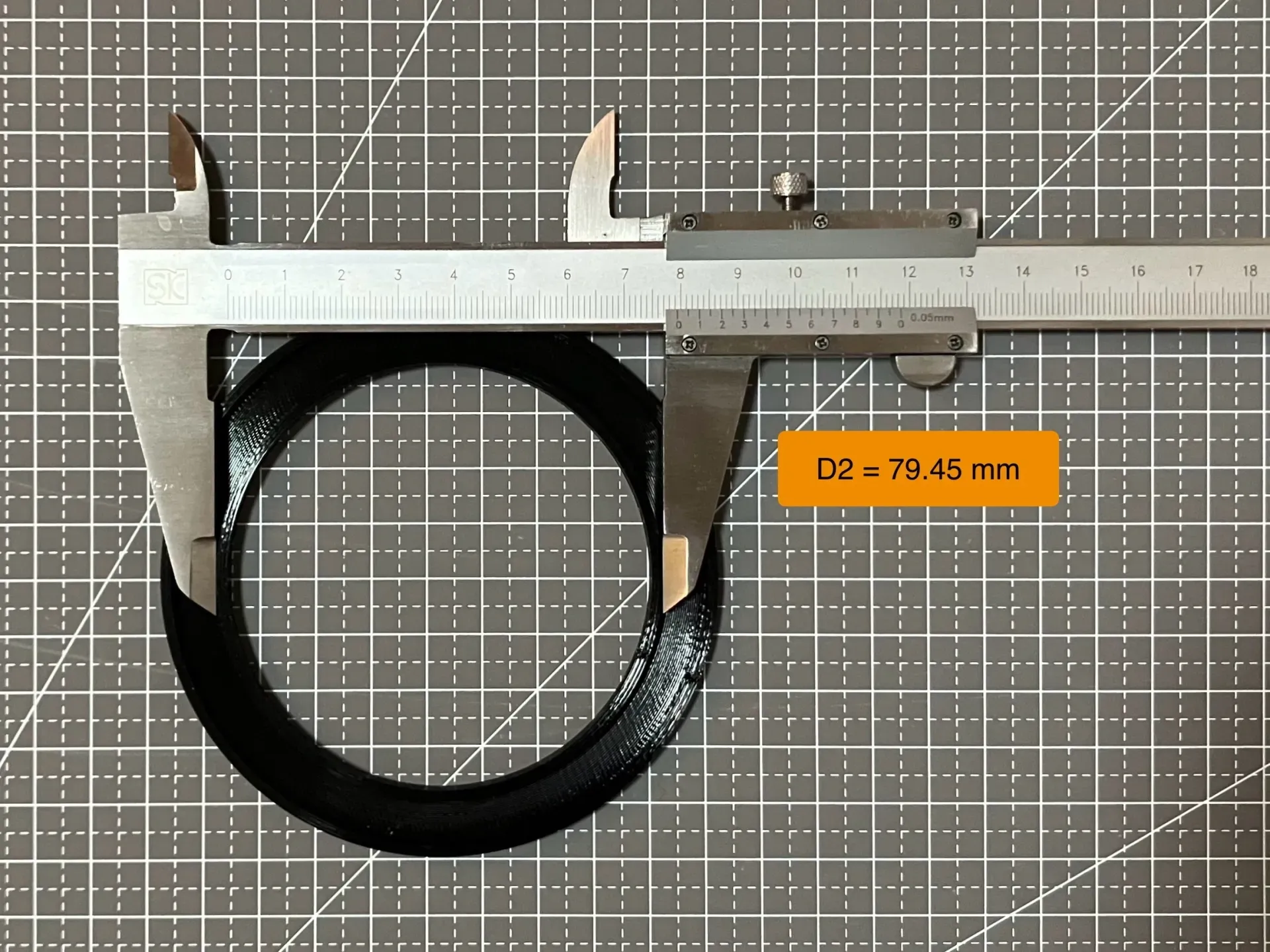
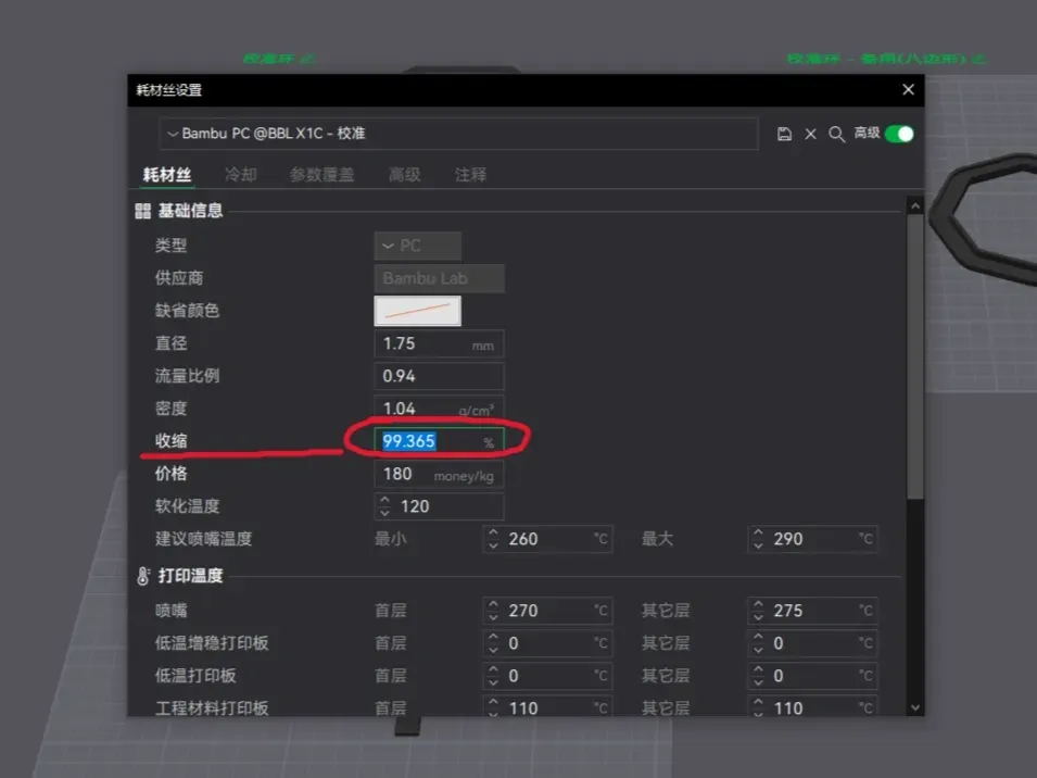
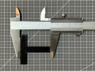
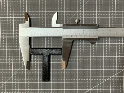
The calculated shrinkage rate is 99.365%
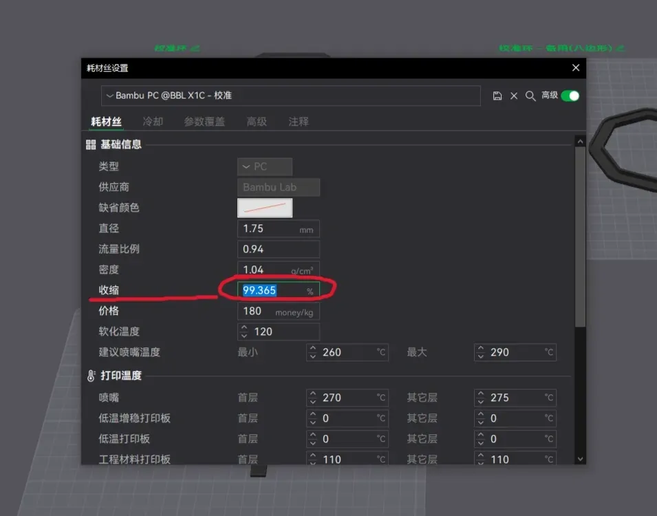
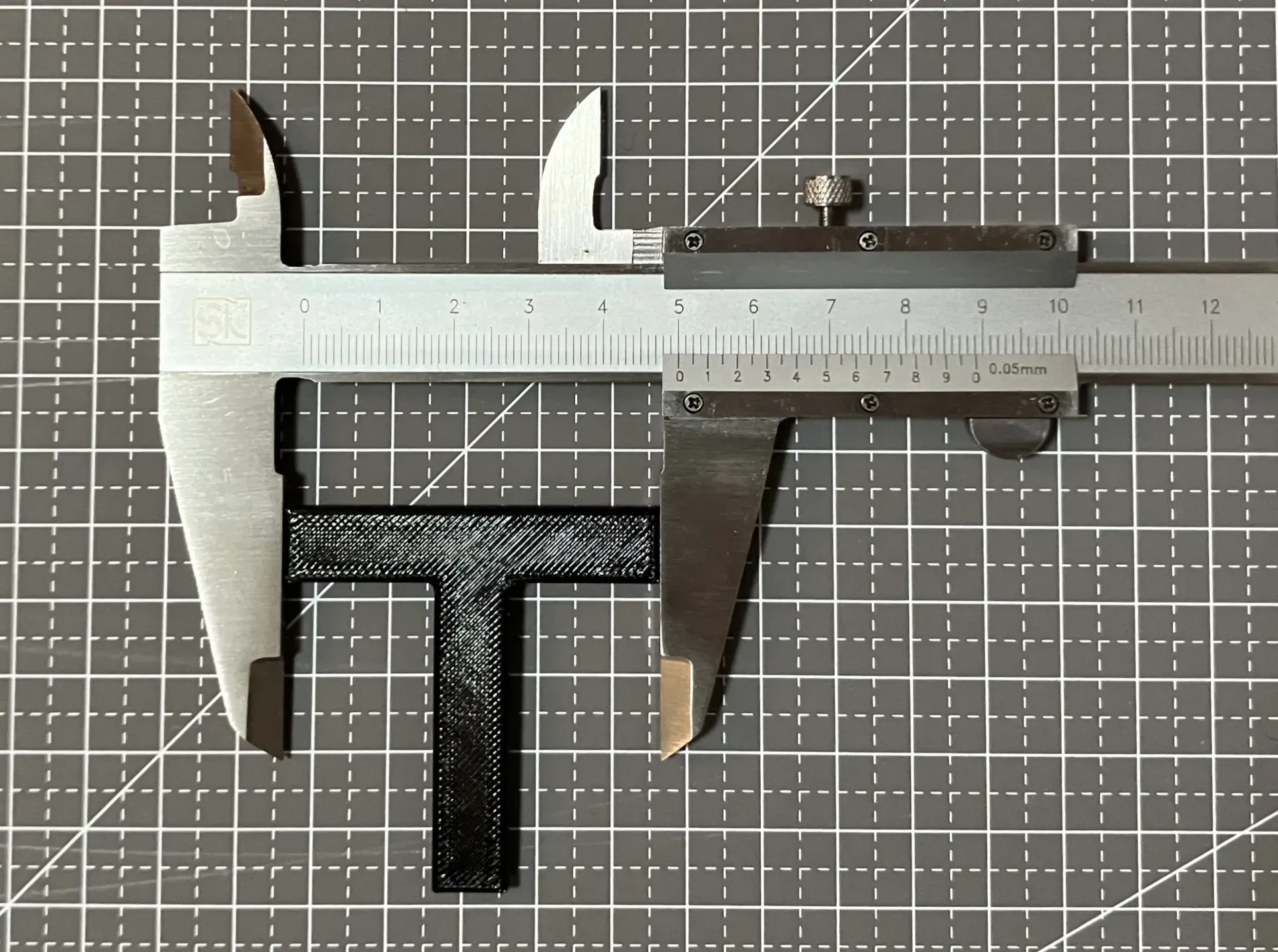
Reprinting the test ring and sample yields the following calibration results:
~~~~~~~~~~ Approximate Shrinkage Rates for Common Filaments ~~~~~~~~~~
- Bambu PLA Basic : 99.70 %
- Bambu PLA Matte : 99.70 %
- Bambu PLA Glow : 99.70 %
- Bambu PLA Silk : 99.75 %
- Bambu PLA-CF : 99.75 %
- Bambu PC : 99.35 %
- Bambu ASA : 99.30%
~~~~~~~~~~ End ~~~~~~~~~~
License

You shall not share, sub-license, sell, rent, host, transfer, or distribute in any way the digital or 3D printed versions of this object, nor any other derivative work of this object in its digital or physical format (including - but not limited to - remixes of this object, and hosting on other digital platforms). The objects may not be used without permission in any way whatsoever in which you charge money, or collect fees.


Comment & Rating (11)