Free-flight glider "Albatross"


Print Profile(2)


Description
SIMPLE. FLYING. FUN.
Albatross V2 — Refined Flight, Extended Possibilities
After months of testing and refinement, the model’s design has been improved.
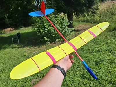
The current V2 configuration of the Albatross introduces a number of updates aimed at enhancing flight performance, stability, and usability. Thanks to its increased wingspan and updated wing geometry, the model now offers a noticeably smoother and more sustained glide. Compared to other models in its class, a well-trimmed Albatross delivers a surprisingly graceful soaring experience — reminiscent of flying a real glider.
The modular construction remains compact and transport-friendly while allowing precise tuning of balance and control surfaces. Whether used for relaxed flights or experimentation with aerodynamic settings, the updated Albatross combines simplicity with elegance in the air.
Available configurations:
- V1 - OBSOLETE design);
- V2 - new design with movable Wing;
- V2 SW (Short Wing) - new design with movable Wing, optimized for A1mini printer.
1 – Model Description
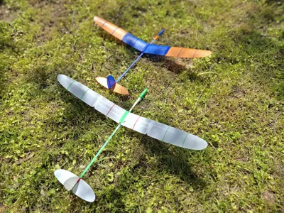
"Albatross" is a compact free-flying glider model for outdoor launches in calm weather. Model offers an excellent hands-on introduction to the basic principles of aircraft design, technology and flight mechanics.
The model has a wingspan of 770 mm, length of 558 mm, and weighs approximately 88 grams. Model has an improved design of Wing and has a movable wing position. This option provides the ability for very precise adjustment of the model’s aerodynamic focus and center of gravity, ensuring the most optimal, long-lasting, and beautiful flight.
To assemble “Albatross” follow the instruction steps below.
2 - Model Assembly
The model consists of 18 parts, as shown in Figure 1.

1 – Balancer, 2 – Nose connector, 3 – Nose bracket, 4 – Beam A, 5 – Beam connector, 6 – Beam B, 7 – Tail connector, 8 – Vertical fin, 9 – Right stabilizer, 10 – Left stabilizer, 11 – Wing bracket, 12 – Wing Center Section, 13 – Center Section Rib, 14 – Wing Connector, 15 – Left wing, 16 – Right wing, 17 – Large rib, 18 – Small rib.
Version V2 SW has only 1 rib per Wing. The principle of assembly is same.
Glue must be used where indicated by a special symbol. It is recommended to perform a first test assembly without glue to understand the assembly principles and check the fit of parts. Final assembly before flight must be done with glue. SuperGlue is recommended.

Assemble the nose section (parts 1, 2, 3).
Assemble the boom (parts 4, 5, 6) — glue must be used during beam assembly.

Connect the assembled boom to the nose section (join parts 4 and 3).
The special markers on part 4 should face downward during assembly, symmetrically on both the right and left sides. Using glue for this connection is optional. However, if there is a significant gap, glue may be used to secure the parts.

When installing the stabilizer or vertical fin, first insert its front end, then rotate it into the final position. A test assembly is recommended before applying glue. For the final assembly, be sure to use glue.

Glue the assembled tail unit to the tail boom.

Assemble the wing. Install the wing center section (12) into the wing bracket (11). When installing the wing center section, first insert the front part, then rotate it into its final position. A test fit is recommended before applying glue. During assembly, make sure there are no gaps at the front section and that the parts are aligned correctly, as shown in the picture. For the final assembly, be sure to use glue.

Install the ribs onto the wing central part. The ribs are placed into specially designed slots on the leading and trailing edges. Before installation, ensure that the ribs are positioned in the correct orientation relative to the direction of flight, following the curve of the wing bracket. For the initial installation of rib (13), the panel needs to be slightly compressed to give it curvature, as shown in Figure 18. Rib 13 is the longest of all the ribs.

After positioning the rib on the panel, slide it toward the center for final installation. A click will be heard when it is properly installed. No glue is used when installing the ribs.

Install the wing connector (14) as shown in Figures 21 and 22. When installing the wing connector, first insert the front part, then rotate it into its final position. A test fit is recommended before applying glue. During assembly, make sure there are no gaps at the front section and that the parts are aligned correctly, as shown in the diagram. For the final assembly, be sure to use glue.

Install the left wing (15) into the assembled wing center section. When installing the wing, first insert the front part, then rotate it into its final position. A test fit is recommended before applying glue. During assembly, make sure there are no gaps at the front section and that the parts are aligned correctly, as shown in the diagram. For the final assembly, be sure to use glue.

Install the ribs onto the wing. The ribs fit into specially designed slots on the leading and trailing edges. A click will be heard when they are properly installed. Ensure that the ribs are oriented correctly relative to the direction of flight, following the curvature of the wing bracket. Start with the larger rib (part 17), then install the smaller rib (part 18). No glue is used when installing the ribs.
Repeat all wing assembly steps for the right side, using parts 12, 13, 14, 16, 17, and 18.

The assembled wing is shown in Figure 27. The completed wing should have no warping of the lifting surface and must be symmetrical.

The wing installation is very simple using any office rubber band, as shown in the illustration.
The wing can be moved forward or backward if needed, allowing for precise adjustment of the model’s Center of Gravity.
Additionally, if necessary, model components (the wing or fuselage) can be disassembled for convenient and compact transportation or components fast replacement.
3- Model Pre-flight Adjustment
Before the first flight, it is strongly recommended to balance the model to expedite its in-flight adjustment. The initial CG position must be adjusted to approximately 20-23 mm from the wing leading edge. Special mounting points for setting up on a balancing stand are provided for initial adjustment, as shown in Figures 30 and 31.

For static balance, simply move the installed wing forward and backward and check the position of the center of gravity on the stand. The balanced model should be in static equilibrium or with a slight nose-down inclination.
The following CG Balancing Stand (as shown on picture) may be used: https://makerworld.com/en/models/912400-model-cg-balancing-stand#profileId-873575
Alternatively, model balance can be adjusted in hands, allocating the marked point of wing center sections on the fingers.
4 - Model Flight
The model is launched outdoors. It is recommended to launch the model in relatively calm weather, with winds no stronger than 9 km/h (2.5 m/s, 5 knots).
The model is launched horizontally or with a slight nose-down inclination (about 2-3 degrees) with a gentle push. The model should be launched directly into the wind.
In case of diving (model with a “heavy nose”) or pitching up, it is necessary to further adjust the position of the model’s center of gravity.
Pitch adjustment is achieved by slightly moving the wing forward (to pitch up in case of a “heavy nose”) or rearward (to pitch down). Yaw adjustment is achieved by deflecting the rudder.
Happy Flights and Smooth Landings!
Boost Me (for free)
If you like my models, hit that Boost button like it's a launch switch! 🚀
License
You shall not share, sub-license, sell, rent, host, transfer, or distribute in any way the digital or 3D printed versions of this object, nor any other derivative work of this object in its digital or physical format (including - but not limited to - remixes of this object, and hosting on other digital platforms). The objects may not be used without permission in any way whatsoever in which you charge money, or collect fees.
Comment & Rating (413)