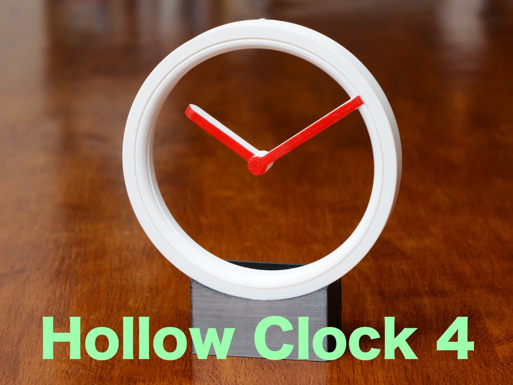
Hollow Clock 4 Remix


Print Profile(2)


Description
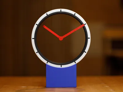
This clock is a remix of Hollow Clock 4, one of the amazing designs by Shiura. I prefer the narrow-beam look of this design over his improved Hollow Clock V. In this remix, I have incorporated what I liked best from both designs and added some of my own improvements. I also designed optional improved electronics with significantly greater timekeeping accuracy and no humming noise when the motor moves the clock hands. See end of these instructions for details.
New or remixed files compared to the original Hollow Clock 4:
- Front Cover.stl — redesigned to fit rotors more precisely; added tick marks to face
- Back Cover.stl — incorporated Hollow Clock V’s snap-fit design
- Gear Holders.stl — new gear support system to decrease looseness of the gear mechanism
- Worm Gear.stl — shortened shaft to fit new gear support system
- Bevel Gear.stl — scaled to correctly fit worm gear
- Front Gear Washer.stl — redesigned to fit gear shaft properly
- Base for ULN Driver.stl — new, slightly narrower two-level base design to fit Hollow Clock V’s improved electronics
Required Non-Printed Materials (All products shown or mentioned are items that I actually use and have found to work well. I have no relationship with any product supplier.)
- Waveshare RP2040-Zero microcontroller board without pin headers
- 28BYJ-48 5V geared stepper motor with ULN2003 driver board
- USB-C 5V power supply, such as a cell phone charger
- (5) M2 self-tapping pan head screws, 5 mm length; for example: Amazon
- (2) M3 self-tapping pan head screws, 4 or 5 mm length; found in kit above
- (1) M2 self-tapping pan head screw, 10 mm length; for example: Amazon
- Glue — two-part epoxy is best for this project, but cyanoacrylate (“Super”) glue would also work
Print files. In addition to the 3MF file, the individual STL files are also included for those with other printer brands. Some parts require non-default settings:
- Front Cover.stl — split to parts, 3 wall loops, 5 bottom shell layers, to prevent show-through of color layer
- Base.stl — gyroid infill pattern to avoid visible striations
Assembly Video
Electronics Preparation — More Detailed Instructions
| Step 1a. Clip/trim the driver board’s 4-pin header, leaving about 2 mm of each pin. | Step 1b. Solder pads 2, 3, 4, and 5 of the controller board onto the driver board’s 4-pin header. The boards must be level in order to fit the enclosure properly. | Step 1c. Solder the controller board’s 5V and GND pads to the driver board’s (+) and (–) pads, respectively. |
 |  |  |
| Step 2a. Clip one “ear” off the stepper motor. Make an indentation with wire cutters, then bend off with pliers. | Step 2b. Place the driver board into the slot at the bottom rear of the clock base. Screw down the board with two short M3 screws. Plug in the motor. |
 |  |
Programming
Software Installation
Program Modifications — At the top of mystery-clock-uln.ino, there are constants that you can edit to change the program’s behavior.
|
Improved Electronics Design on GitHub (optional)
Improved Electronics
I designed a custom electronics board that is 15 times more accurate at timekeeping than the RP2040 microcontroller alone. The custom board also eliminates the stepper motor’s audible hum when it moves the clock hands. The board has 2 pushbuttons that allow fine adjustments of the hand positions.
Making the board requires soldering and basic knowledge of electronic parts. Complete instructions and board design files are available on GitHub. The updated print profile includes an alternate base that fits the custom board. |  |
Comment & Rating (30)