Pinball style Clock


Print Profile(1)

Bill of Materials
- ArduinoNano x 2:
- RTCDS3231 x 1:
- 28BYJ-48 x 4: including_driver_board
- Microswith x 4:
- Button x 5:
- Powersupply x 1: >3A
- WS2812B_LEDstrip x 1: 6_Pixels
- Wires_and_connectors x 1:
- Prototype_PCB's x 1:
- M4_Nuts x 14:
- M2_Nuts x 12:
- M4x10 x 18:
- M2x10 x 16:
- M3x10 x 16:
Description
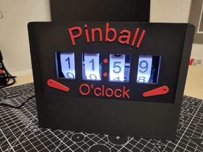
This is my project for the bambulab clock contest.
It is inspired by the scorewheels of electromechanical pinball machines.
The clock is using 4 score wheels mounted on 28BJY-48 Stepper motors for displaying the time.
When setting up the clock, it has to be homed. Therefore the homing button needs to be pressed around 5s. All 4 wheels will drive to 0 position.
This will also reset the used RTC to 00:00.
The time can be adjsuted by holding the Set button for 5 sec.
Afterwards the time adjustment is happening by pressing the + button. with the Set button you can switch between the wheels for the setup.
After adjusting the last wheel, another press on the Set button will bring the clock back to operating mode.
There are 6 different LED Modes also brightness can be adjusted in 3 different modes (low, medium, high).
I split up the code on 2 arduino (1x for logic 1x for driving the stepper).
Following electronic components are needed:
2x Arduino Nano
1x RTC Module DS3231
4x 28BYJ-48 Stepper + 4x ULN2003 driver board
4x Microswitch
5x Button
1x WS2812B LED strip with 6 pixels
1x 0,1uf condensator for LED strip (optional)
1x 10k resistor for dataline of LED strip (optional)
1x power supply 5v with >3A
1x connector for power supply
1x 5x7cm Prototype PCB (optional)
1x 2x8cm Prototype PCB (optional)
Assembling:

Insert the M4 nuts in the cutouts

Insert M2 nuts on all counter parts for microswitches and for the Button PCB mount

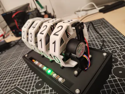
Install stepper and microswitches in the stepper mount

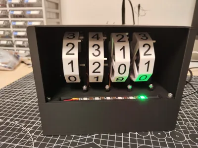
Install score wheels

Adjust Microswitch position, that it is triggered when showing 0

Mount the scorwheels and Solder all components on the board

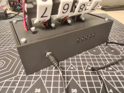
Mount the electronic boards on the PCB mounting part

Install heat inserts in the bottom case and screw donw the PCB board (don't forget to insert buttons first)

Connect score board and mount it down with M4 screws

It should look like that now

Install top cover and front plate
Here is the connection plan for the electronics:
| Arduino 1 | Arduino 2 | ||
| Pin | Connection | Pin | Connection |
| D0 | D0 | ||
| D1 | D1 | ||
| D2 | Button Plus | D2 | In1 Minute Unit driver board |
| D3 | Button Set | D3 | IN2 Minute Unit driver board |
| D4 | Button Home | D4 | In3 Minute Unit driver board |
| D5 | Button LED Brightness | D5 | In4 Minute Unit driver board |
| D6 | Button LED Mode | D6 | In1 Minute Tens driver board |
| D7 | Microswitch Step1 | D7 | IN2 Minute Tens driver board |
| D8 | Microswitch Step2 | D8 | In3 Minute Tens driver board |
| D9 | Microswitch Step3 | D9 | In4 Minute Tens driver board |
| D10 | Microswitch Step4 | D10 | In1 Hours Unit driver board |
| D11 | D11 | IN2 Hours Unit driver board | |
| D12 | D12 | In3 HoursUnit driver board | |
| D13 | WS2812B LED 6 pixel | D13 | In4 Hours Unit driver board |
| A0 | A0 | In1 Hours Tens driver board | |
| A1 | A1 | IN2 Hours Tens driver board | |
| A2 | A2 | In3 Hours Tens driver board | |
| A3 | A3 | In4 Hours Tens driver board | |
| A4 | RTC SDA | A4 | |
| A5 | RTC SCL | A5 | |
| A6 | A6 | ||
| A7 | A7 | ||
| TX1 | Arduino 2 RX0 | TX1 | Arduino 1 RX0 |
| RX0 | Arduino 2 TX1 | RX0 | Arduino 1 TX1 |
| VIN | 5V power Suppply | VIN | 5V power Suppply |
| GND | Ground | GND | Ground |
Please not that the RX/TX connection must be opened in order to be able for updating code.
Therefore I installed jumpers at my prototype PCB.
Note: The code is not final yet. It still needs to be optimized a bit, but a basically it is working.
Documentation (2)
License
You shall not share, sub-license, sell, rent, host, transfer, or distribute in any way the digital or 3D printed versions of this object, nor any other derivative work of this object in its digital or physical format (including - but not limited to - remixes of this object, and hosting on other digital platforms). The objects may not be used without permission in any way whatsoever in which you charge money, or collect fees.
Comment & Rating (2)