Search models, users, collections, and posts
Optical Sensor Switch for Mr Bullet Feeder Dies v2
IP Report


Print Profile(1)

0.2mm layer, 2 walls, 15% infill
Designer
6.2 h
2 plates
Open in Bambu Studio
Boost
30
119
36
17
179
78
Released
Description
Boost Me (for free)
If you like my models consider giving me a boost. It's much appreciated!
The optical bullet switch works with my Dillon XL650 XL750 Bullet Feeder V2
This is a bullet feeder switch that works with an optical sensor. No micro switch needed. I did not use a set screw as the weight should be enough to keep it on the die.
This is a big improvement over my last optical switch.
ALL NEW IN V2:
- Now connects using a standard 4-pole headphone cord. No more delicate JXT connectors!
- No longer requires the campanion control box
- Now has a visual port for the LED
- Now has an adjustment port for the photocell
- Insert sleeves are now dropped in from the top instead of the bottom of the switch body
Details:
- Set to accept up to .45 ACP
- Includes inserts for 9mm and .223
- Input side is sized to accept 12mm slinky hose
- Includes adaptor to accept 10mm slinky hose
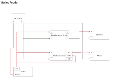
Wiring instructions:
- Connect 1x 5730 LED chip to the buck convertor and set the convert to it's lowest setting where the light turns on
- Combine the positive leads from the optical sensor and the buck convertor to the 4-pole headphone jack
- Combine the negative leads from the optical sensor and the buck convertor to the 4-pole headphone jack
- The green and white leads are connected to the breaker and then connected to your bullet feeder motor through the 4-pole headphone jack. When the light beam is interupted by the bullets, this breaker will turn off the bullet feeder.
This switch connects directly to the bullet feeder through the headphone jack.
Materials used:
- LED Chips - https://www.amazon.com/gp/product/B09XB5KDWS
- Photo Sensor Relay - https://www.amazon.com/gp/product/B073XL5161
- 10mm Slinky - https://www.amazon.com/gp/product/B08BJC5JPF
- 12mm Slinky - https://www.doublealpha.biz/us/mrbulletfeeder-output-spring-and-extension-adaptor
- Buck Convertor - https://www.amazon.com/gp/product/B07PDGG84B
- M3 Screws - https://www.amazon.com/gp/product/B0188DMF3A
- M3 Inserts - https://www.amazon.com/gp/product/B08BJD3W4X
- Headphone Jacks - https://www.amazon.com/dp/B06XG3YTC4
- Headphone Cord - https://www.amazon.com/gp/product/B08KSTBQ27
- 12V Power Barrel Socket - https://www.amazon.com/dp/B01N8VV78D
View all my models here.

License
This user content is licensed under a
Creative Commons Attribution-Noncommercial-Share Alike
Comment & Rating (36)